Light-weighting of a Structural Beam: Generative Design using Topology Optimisation
- kristan209
- Feb 18, 2022
- 2 min read
Updated: May 3, 2022
“Effective #design #optimisation lies is in achieving the correct balance between the design solution, the chosen manufacture process and target cost of manufacture.”
The Challenge
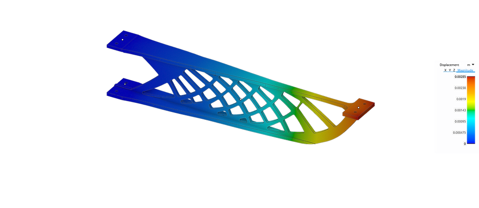
We were tasked with minimising the weight of a cantilever beam constructed from an aluminium 6061 T6 I-beam. It was required to withstand a load of 1 tonne with a maximum deflection of 3 mm at its end. The final solution was required to suit CNC machining fabrication methods.
Aluminium 6061T6, I Beam
Dimensions: 203.2 x 114.3 mm, Flange 12.7mm, Rib 11.1 mm
Load case: 1000 kg end load.
Deflection target: Maximum displacement limit 3mm.
Our Solution
We employed a #generativedesign approach using #topologyoptimisation to discover where material could be removed from the structure to optimise the stiffness vs weight for the I beam under the set target criteria.
The Process:
CAD generation and FEA of I-Beam model
Add topology optimisation constraints & run simulations (assess output and re-run, if necessary, with adjusted constraints)
Reverse engineer topology mesh into CAD model for downstream manufacturing.
FEA of final CAD model to assess against target goals.
1. CAD Generation and FEA Analysis of I-Beam

Initial Model Constraints
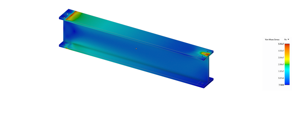
I Beam FEA
I-Beam Analysis:
Weight saving 0%
Maximum displacement 1.6 mm (Safety Factor 4.4)
2. Topology Optimisation
Apply constraints, bounding volume and manufacturing constraints for optimisation algorithms
Video of Topology Optimisation Process
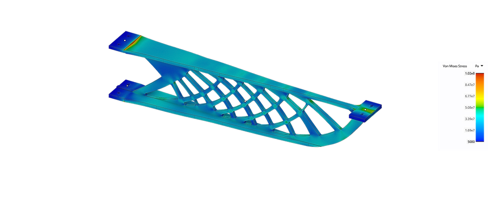
Topology Optimised design of the I-beam structure – image of Von Mises Stress
The topology optimised solution:
Weight saving 59% over the original I beam.
Maximum displacement 3.2 mm
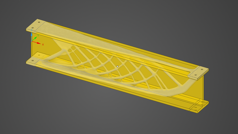
Overlay of #Topologyoptimised design on top of the original I-Beam geometry
3. Design for Manufacture
The output from the topology optimisation process was #reverseengineered to align to a 3-axis cnc machining process. This reverse engineering process required simplification of the mesh geometry to achieve cost efficiencies and final target deflection criteria.
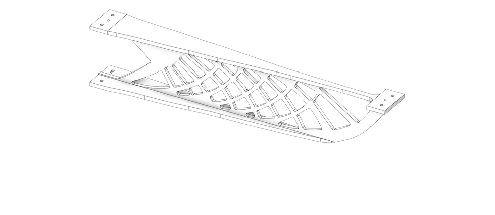
Reverse engineered solution developed for a cost effective 3-axis CNC machining process.
4. Validation

FEA analysis of final CAD solution for validation against original structural design goals.
The #TopologyOptimised solution with manufacture constraints:
Weight saving 55% over the original I beam.
Maximum displacement 2.85 mm (Safety Factor 2.55) PASS

Comentários